Diagnostics of the motherboard

The FA100 motherboard diagnostics section shows a reproduction of the board with details of the terminals.
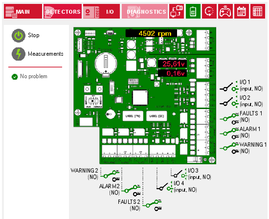
The  button on the left starts a direct connection with the FA100 which provides the opportunity to view the status of the terminals in real time and the presence of faults, possibly signalled with an icon alongside (
 ,
,  ,
,  ).
).
Faults
Possible faults signalled:
-
“Corrupt programming”, the programming data is incorrect, missing or not present, so the device may operate as expected. It is necessary to reprogram the device.
-
“Firmware update failed”, the update procedure was interrupted or failed. It is necessary to retry the update procedure.
-
“Supervision fault”, the voltage on a terminal exceeds the programmed supervision thresholds, therefore the terminal is short-circuited or open. The device is operating correctly but the programming linked to the terminal is temporarily deactivated
-
“Service mode”, the device is in maintenance mode therefore it is operating correctly but cannot generate any type of signalling, neither for specific faults nor alarms. By default, when in Service mode, the fault relays are activated and the aspirating system is operative, however these behaviours can be modified by means of the appropriate programming options.
-
“Aspirator fault” indicates failure of the fan. The device is operating correctly but the aspirator fan is not spinning at the programmed speed. Checking the fan connector is recommended.
In these cases, a “Low flow fault” is also displayed but such a fault also occurs in the event of an obstruction in the system.
-
"Loop fault”, it occurs when the loop is no longer reachable or has been enabled and not yet connected. In this case, it is necessary to check the connection with the control panel and verify that it is operating correctly.
-
“Loop Isolator Open”, it occurs when the device detects a shorted or open circuit on the connection with the loop.
-
“Primary power fault”, it occurs when the Mains power is below the minimum threshold value. The device will continue to operate correctly however the fault will be signalled. Check the connection and functionality of the primary power supply.
-
“Ancillary power fault”, it occurs if the secondary power supply has been enabled but is lower than the minimum threshold value. The device will continue to operate correctly however the fault will be signalled. Check the programming or the connection and functionality of the secondary power supply.
Terminals
There is a label for each terminal with the description, type of terminal (input, output or relay) and polarity (N.C. / N.O.).
An icon is also associated whose colour represents the status of activation (stand-by, active, fault).
Status of input terminals:
|
polarity |
stand-by |
active |
open circuit |
short circuit |
|---|---|---|---|---|
|
N.O. |
|
|
|
|
|
N.C. |
|
|
|
|


Status of output terminals:
|
polarity |
stand-by |
active |
fault |
|---|---|---|---|
|
N.O. |
|
|
|
|
N.C. |
|
|
|


Status of relay output terminals:
|
polarity |
stand-by |
active |
fault |
|---|---|---|---|
|
N.O. |
|
|
|
|
N.C. |
|
|
|


The  button on the left starts the reading of the fan speed (RPM), the voltage supplied by the primary and ancillary power sources.